14
Remote/Local Temperature Sensor
with SMBus Serial Interface
MAX1617
Maxim Integrated
Slave Addresses
The MAX1617 appears to the SMBus as one device
having a common address for both ADC channels. The
device address can be set to one of nine different val-
ues by pin-strapping ADD0 and ADD1 so that more
than one MAX1617 can reside on the same bus without
address conflicts (Table 9).
The address pin states are checked at POR only, and
the address data stays latched to reduce quiescent
supply current due to the bias current needed for high-Z
state detection.
The MAX1617 also responds to the SMBus Alert
Response slave address (see the Alert Response
Address section).
POR and UVLO
The MAX1617 has a volatile memory. To prevent ambigu-
ous power-supply conditions from corrupting the data in
memory and causing erratic behavior, a POR voltage
detector monitors V
CC
and clears the memory if V
CC
falls
below 1.7V (typical, see Electrical Characteristics table).
When power is first applied and V
CC
rises above 1.75V
(typical), the logic blocks begin operating, although reads
and writes at V
CC
levels below 3V are not recommended.
A second V
CC
comparator, the ADC UVLO comparator,
prevents the ADC from converting until there is sufficient
headroom (V
CC
= 2.8V typical).
Power-Up Defaults:
" Interrupt latch is cleared.
" Address select pins are sampled.
" ADC begins auto-converting at a 0.25Hz rate.
" Command byte is set to 00h to facilitate quick
remote Receive Byte queries.
" T
HIGH
and T
LOW
registers are set to max and min
limits, respectively.
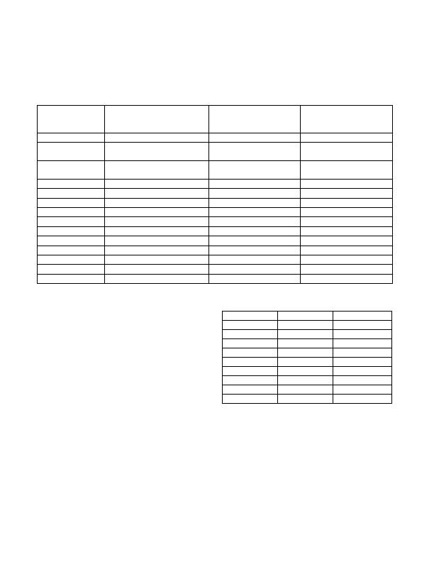
Table 8. RLTS and RRTE Temp Register Update Timing Chart
n/a (0.25Hz)
NEW CONVERSION RATE
(CHANGED VIA WRITE TO
WCRW)
Power-on reset
Auto-Convert
OPERATING MODE
CONVERSION INITIATED BY:
156ms max
TIME UNTIL RLTS AND RRTE
ARE UPDATED
156ms max
n/a
1-shot command, while idling
between automatic conversions
Auto-Convert
When current conversion is
complete (1-shot is ignored)
20sec
n/a
0.0625Hz
Rate timer
Auto-Convert
1-shot command that occurs
during a conversion
Auto-Convert
10sec
5sec
0.125Hz
0.25Hz
Rate timer
Auto-Convert
2.5sec
1.25sec
0.5Hz
1Hz
Rate timer
Auto-Convert
Rate timer
Auto-Convert
Rate timer
Auto-Convert
625ms
312.5ms
2Hz
4Hz
Rate timer
Auto-Convert
237.5ms
156ms
8Hz
n/a
STBY pin
Hardware Standby
Rate timer
Auto-Convert
Rate timer
Auto-Convert
156ms
156ms
n/a
n/a
1-shot command
Software Standby
RUN/STOP bit
Software Standby
Table 9. Slave Address Decoding (ADD0
and ADD1)
Note: High-Z means that the pin is left unconnected.
0011 001
High-Z
GND
0011 000
ADDRESS
0101 001
GND
High-Z
0011 010
V
CC
GND
0101 011
V
CC
High-Z
0101 010
1001 101
High-Z
V
CC
1001 100
GND
GND
GND
V
CC
High-Z
High-Z
1001 110
V
CC
V
CC
ADD0
ADD1
发布紧急采购,3分钟左右您将得到回复。
相关PDF资料
MAX1619MEE+
IC TEMP SENSOR W/ALARM 16-QSOP
MAX1765EUE+
IC REG DL BST/LINEAR 16TSSOP
MAX1989MUE+
IC TEMP SENSOR REMOTE 16TSSOP
MAX31723MUA+
IC THERMOMETER/STAT SPI-3W 8UMAX
MAX31826MUA+T
IC TEMP SENSOR DIGITAL 8UMAX
MAX4006EUT+T
IC CURRENT MONITOR 1% SOT23-6
MAX4008EUT+T
IC CURRENT MONITOR 1% SOT23-6
MAX4370ESA+T
IC CNTRLR HOT-SWAP 8-SOIC
相关代理商/技术参数
MAX1617MEE+TW
功能描述:板上安装温度传感器 Remote/Local Temperature Sensor with SMBus Serial Interface RoHS:否 制造商:Omron Electronics 输出类型:Digital 配置: 准确性:+/- 1.5 C, +/- 3 C 温度阈值: 数字输出 - 总线接口:2-Wire, I2C, SMBus 电源电压-最大:5.5 V 电源电压-最小:4.5 V 最大工作温度:+ 50 C 最小工作温度:0 C 关闭: 安装风格: 封装 / 箱体: 设备功能:Temperature and Humidity Sensor
MAX1617MEE+W
功能描述:板上安装温度传感器 Remote/Local Temperature Sensor with SMBus Serial Interface RoHS:否 制造商:Omron Electronics 输出类型:Digital 配置: 准确性:+/- 1.5 C, +/- 3 C 温度阈值: 数字输出 - 总线接口:2-Wire, I2C, SMBus 电源电压-最大:5.5 V 电源电压-最小:4.5 V 最大工作温度:+ 50 C 最小工作温度:0 C 关闭: 安装风格: 封装 / 箱体: 设备功能:Temperature and Humidity Sensor
MAX1617MEE-T
功能描述:板上安装温度传感器 RoHS:否 制造商:Omron Electronics 输出类型:Digital 配置: 准确性:+/- 1.5 C, +/- 3 C 温度阈值: 数字输出 - 总线接口:2-Wire, I2C, SMBus 电源电压-最大:5.5 V 电源电压-最小:4.5 V 最大工作温度:+ 50 C 最小工作温度:0 C 关闭: 安装风格: 封装 / 箱体: 设备功能:Temperature and Humidity Sensor
MAX1617MEE-TG075
制造商:Maxim Integrated Products 功能描述:
MAX1618EVKIT
制造商:Maxim Integrated Products 功能描述:REMOTE TEMPERATURE SENSOR WITH SMBUS SERIAL I - Bulk
MAX1618MUB
功能描述:板上安装温度传感器 Sensors, Transducers RoHS:否 制造商:Omron Electronics 输出类型:Digital 配置: 准确性:+/- 1.5 C, +/- 3 C 温度阈值: 数字输出 - 总线接口:2-Wire, I2C, SMBus 电源电压-最大:5.5 V 电源电压-最小:4.5 V 最大工作温度:+ 50 C 最小工作温度:0 C 关闭: 安装风格: 封装 / 箱体: 设备功能:Temperature and Humidity Sensor
MAX1618MUB+
功能描述:板上安装温度传感器 RoHS:否 制造商:Omron Electronics 输出类型:Digital 配置: 准确性:+/- 1.5 C, +/- 3 C 温度阈值: 数字输出 - 总线接口:2-Wire, I2C, SMBus 电源电压-最大:5.5 V 电源电压-最小:4.5 V 最大工作温度:+ 50 C 最小工作温度:0 C 关闭: 安装风格: 封装 / 箱体: 设备功能:Temperature and Humidity Sensor
MAX1618MUB+T
功能描述:板上安装温度传感器 Sensors, Transducers RoHS:否 制造商:Omron Electronics 输出类型:Digital 配置: 准确性:+/- 1.5 C, +/- 3 C 温度阈值: 数字输出 - 总线接口:2-Wire, I2C, SMBus 电源电压-最大:5.5 V 电源电压-最小:4.5 V 最大工作温度:+ 50 C 最小工作温度:0 C 关闭: 安装风格: 封装 / 箱体: 设备功能:Temperature and Humidity Sensor
